Home>Production & Technology>Metronome>How To Build A Simple Metronome

Metronome
How To Build A Simple Metronome
Published: January 13, 2024
Learn how to build a metronome with this simple guide. Perfect for musicians and anyone looking to improve their rhythm and timing.
(Many of the links in this article redirect to a specific reviewed product. Your purchase of these products through affiliate links helps to generate commission for AudioLover.com, at no extra cost. Learn more)
Table of Contents
Introduction
Welcome to this step-by-step guide on how to build a simple metronome! If you’re a musician looking to improve your timing and rhythm, a metronome can be an invaluable tool. Not only can it help you stay in tempo while practicing, but it can also assist with developing a strong internal sense of timing.
A metronome is a device that produces regular beats at a specific tempo, acting as a musical timekeeper. While there are many metronome apps available on smartphones, building your own metronome can be a fun and rewarding project. Plus, it allows you to customize its features and aesthetics to suit your preferences.
In this guide, we’ll show you how to build a simple metronome using an Arduino microcontroller. Arduino is an open-source electronics platform that allows you to create interactive projects by programming it to control different components. By following the steps provided, you’ll be able to assemble the circuit, program the Arduino, build the enclosure, and test your newly created metronome.
Even if you’re new to electronics and programming, don’t worry! We’ll guide you through the process with clear explanations and straightforward instructions. So, gather your materials, put on your creative hat, and let’s get started on building your very own metronome!
Materials Needed
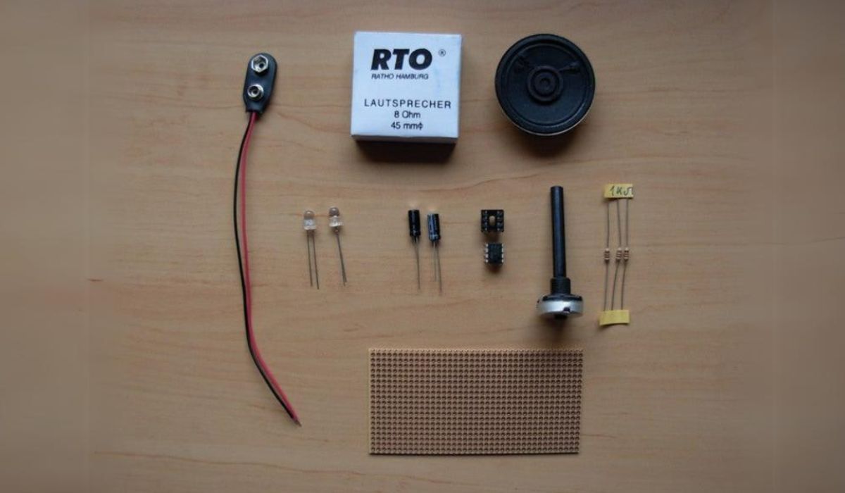
Before we dive into the construction of our metronome, let’s gather all the necessary materials. Here’s a list of items you’ll need to complete this project:
- An Arduino board (such as Arduino Uno)
- A breadboard
- An LED (Light Emitting Diode)
- A piezo buzzer
- A potentiometer (10k ohm)
- A push button
- Jumper wires
- A USB cable for connecting the Arduino to your computer
- A computer with the Arduino IDE (Integrated Development Environment) installed
These components are readily available at electronics stores or online platforms. If you’re new to Arduino, don’t worry about the terminologies – we’ll explain each component and its purpose during the assembly process.
The Arduino IDE is the software used to program the Arduino board. It’s available for free download on the Arduino website and supports Windows, macOS, and Linux operating systems. Make sure to install the appropriate version for your computer before proceeding.
Once you have gathered all the materials, you’re ready to move on to the next step: assembling the circuit. So, let’s roll up our sleeves and start building our metronome!
Step 1: Gathering the Components
The first step in building your own metronome is to gather all the necessary components. Here’s a detailed list of the components you’ll need:
- Arduino board (such as Arduino Uno): This is the main microcontroller board that will control the metronome.
- Breadboard: A breadboard is a platform used for prototyping circuits. It allows you to easily connect and disconnect components without soldering.
- LED (Light Emitting Diode): The LED will act as the visual indicator of the metronome beats.
- Piezo Buzzer: The piezo buzzer will produce the sound for the metronome beats.
- Potentiometer (10k ohm): The potentiometer will be used to control the tempo of the metronome.
- Push Button: The push button will be used to start and stop the metronome.
- Jumper Wires: These wires will be used to connect the components together.
- USB Cable: You’ll need a USB cable to connect the Arduino board to your computer for programming.
- Computer with Arduino IDE: Make sure you have a computer with the Arduino IDE (Integrated Development Environment) installed. This is the software used to program the Arduino board.
Most of these components can be easily found at electronics stores or online retailers. The Arduino board, breadboard, LED, piezo buzzer, potentiometer, and push button are basic components that can be commonly found in Arduino starter kits.
Once you have acquired all the necessary components, you’re ready to move on to the next step: assembling the circuit. In the following section, we’ll guide you through the process of connecting the components on the breadboard and wiring them to the Arduino board.
Step 2: Assembling the Circuit
Now that you have all the components ready, it’s time to assemble the circuit for your metronome. Follow these steps to connect the components on the breadboard:
1. Place the Arduino board at one end of the breadboard. Make sure to align the pins of the Arduino with the breadboard’s power rails.
2. Connect the short leg (cathode) of the LED to one of the Arduino’s digital pins (e.g., pin 13). Connect the longer leg (anode) of the LED to the breadboard’s ground rail.
3. Connect the positive (red) wire of the piezo buzzer to another digital pin of the Arduino (e.g., pin 10). Connect the negative (black) wire of the buzzer to the breadboard’s ground rail.
4. Connect one end of the potentiometer to the 5V pin of the Arduino. Connect the other end of the potentiometer to the ground rail of the breadboard. Finally, connect the middle pin (wiper) of the potentiometer to one of the analog pins of the Arduino (e.g., A0).
5. Connect one side of the push button to the 5V pin of the Arduino. Connect the other side of the button to a digital pin of the Arduino (e.g., pin 2). Finally, connect a 10k ohm pull-down resistor from the same digital pin to the ground rail of the breadboard.
6. Connect a jumper wire from the ground rail of the breadboard to the ground (GND) pin of the Arduino.
7. Connect another jumper wire from the 5V pin of the Arduino to the power rail of the breadboard.
Make sure to double-check your connections and ensure that the components are connected as described above. It’s important to ensure proper connections and avoid loose or incorrect wiring.
In the next step, we’ll proceed with programming the Arduino to control the metronome.
Step 3: Programming the Arduino
With the circuit assembled, it’s time to program the Arduino board to control the metronome. Follow these steps to upload the code to your Arduino:
1. Connect your Arduino board to your computer using a USB cable.
2. Launch the Arduino IDE (Integrated Development Environment) software on your computer.
3. In the Arduino IDE, select the appropriate board from the “Tools” menu. For example, select “Arduino Uno” if you’re using the Arduino Uno board.
4. Choose the correct port from the “Tools” menu. The port should be the one your Arduino board is connected to.
5. Open a new sketch by selecting “File” > “New”.
6. Copy and paste the following code into the Arduino IDE:
cpp
int ledPin = 13;
int buzzerPin = 10;
int potentiometerPin = A0;
int buttonPin = 2;
int tempo;
int beatsPerMinute;
int beatDuration;
void setup() {
pinMode(ledPin, OUTPUT);
pinMode(buzzerPin, OUTPUT);
pinMode(buttonPin, INPUT_PULLUP);
}
void loop() {
if (digitalRead(buttonPin) == LOW) {
tempo = analogRead(potentiometerPin);
beatsPerMinute = map(tempo, 0, 1023, 40, 240);
beatDuration = 60000 / beatsPerMinute;
digitalWrite(ledPin, HIGH);
tone(buzzerPin, 1000, beatDuration);
delay(beatDuration);
digitalWrite(ledPin, LOW);
noTone(buzzerPin);
}
}
7. Verify that there are no syntax errors in the code by clicking the checkmark icon or selecting “Sketch” > “Verify/Compile”.
8. If the code compiles successfully, click the right arrow icon or select “Sketch” > “Upload” to upload the code to the Arduino board.
9. Once the upload is complete, you should see the LED on the Arduino board blink when you press the push button. The piezo buzzer should also produce the sound of the metronome beats.
By default, the code uses the potentiometer to control the tempo of the metronome. Turning the potentiometer knob will adjust the tempo. You can modify the code according to your preferences, such as changing the LED pin, buzzer pin, or button pin.
In the next step, we’ll proceed with building the enclosure for our metronome.
Step 4: Building the Enclosure
To give your metronome a polished and professional look, it’s time to build an enclosure. While the design and materials are entirely up to you, here’s a simple way to create a basic enclosure:
- Choose a suitable container: Select a container that is the right size to house the Arduino board, breadboard, and other components. This could be a project box, a small plastic container, or even a customized 3D-printed enclosure.
- Prepare the container: If needed, drill holes or create openings in the container to accommodate the LED, potentiometer, push button, and any other components you want to expose.
- Mount the components: Secure the Arduino board and breadboard inside the enclosure using screws, double-sided tape, or adhesive. Place the LED, potentiometer, and push button in their designated openings in the container, ensuring they are properly aligned.
- Arrange the wiring: Organize the wires neatly inside the enclosure to minimize clutter and ensure proper connections. Use cable ties or clips to keep the wires in place.
- Close the enclosure: Once everything is in place, close the enclosure and secure it tightly. Make sure the components are protected and won’t be easily damaged.
Remember to leave openings or vents in the enclosure to allow for proper ventilation and prevent overheating of the components.
Feel free to get creative with the enclosure design, paint it, add labels or markings, or even attach a stand for stability. Customizing the enclosure will make it uniquely yours and add a personal touch to your metronome.
With the enclosure completed, let’s move on to the final step: testing and adjusting the metronome.
Step 5: Testing and Adjusting the Metronome
Now that you have built the circuit, programmed the Arduino, and created the enclosure, it’s time to test your metronome and make any necessary adjustments. Follow these steps to ensure everything is working as expected:
- Connect the Arduino board to a power source, such as your computer, using a USB cable. Make sure the power is switched on.
- Turn the potentiometer knob to adjust the tempo. You should see the LED blink and hear the sound of the metronome beats from the buzzer.
- Press the push button to start and stop the metronome. The LED should toggle between on and off states, and the buzzer should produce the beats accordingly.
- Experiment with different tempos and test the accuracy of the beats. Use an external source, such as a digital metronome or a musical instrument with a built-in metronome, to compare the timing. Adjust the potentiometer if necessary to fine-tune the tempo.
If you encounter any issues during the testing phase, double-check the wiring connections, ensure the code is uploaded correctly, and inspect the components for any damage or loose connections.
Once you are satisfied with the functionality and performance of your metronome, you can start using it to enhance your music practice sessions. Use it to improve your timing, work on complex rhythms, or even as a tool for composing and recording.
Congratulations! You have successfully built your own simple metronome from scratch. Enjoy your newfound musical companion and make the most out of your practice sessions!
Before we wrap up, take a moment to celebrate your achievement and appreciate the process of building something useful and creative.
Conclusion
Building a simple metronome using an Arduino microcontroller can be a rewarding and enjoyable project for musicians of all levels. Throughout this step-by-step guide, we have walked you through the process of gathering the necessary components, assembling the circuit, programming the Arduino, building the enclosure, and testing and adjusting the metronome.
By now, you should have a functional metronome that can help you improve your timing and rhythm while practicing and performing. The customization options are endless, allowing you to tailor the metronome to your specific needs and preferences.
Remember, practice makes perfect, and having a reliable metronome by your side can greatly enhance your musical journey. Whether you are a beginner learning the basics or a professional honing your skills, the metronome will serve as a valuable tool for developing your sense of timing and precision.
Feel free to explore and experiment with different features and functionalities. You may consider adding additional controls, adjusting the sound of the beats, or even integrating wireless connectivity to control the metronome remotely.
Building your own metronome is just the beginning of your DIY electronics and programming adventures. As you gain more experience, you can expand your skills to create other exciting projects and explore the endless possibilities of the Arduino platform.
We hope this guide has inspired you to embark on this creative journey and empowered you to construct your own metronome. Enjoy your rhythmic journey and happy music making!

