Home>Production & Technology>Audio Cable Repair and DIY Troubleshooting
Production & Technology
Audio Cable Repair and DIY Troubleshooting
Modified: 3 October 2026
Table of Contents
Understanding your diy audio cables
Before you start any work on DIY audio cables, take a moment to know your audio cable by its connector and its job. A thin plug with two black bands on the tip is a 3.5 mm stereo minijack, the standard consumer headphone format, while a chunky metal barrel with a single band is a 6.35 mm (1/4 inch) TS jack, which carries an unbalanced signal.
One of the most overlooked qualities of a good audio cable is simply using the right format for the environment. A balanced XLR or TRS cable rejects noise over long runs, but an unbalanced TS cable is perfectly fine for a short patch between a guitar and an amp, a pedal, and a desktop interface. This is also the reason audio cables are pricey when you step up to professional stock, as proper braided shielding, durable strain relief, precise contact plating, and exacting plug tolerances all add cost beyond the copper inside.
When you are sizing up a replacement, the standard audio cable size for portable devices and aux inputs is 3.5 mm. The larger 6.35 mm jack remains the norm on studio headphones and mixers and also dominates instrument outputs. Before assuming a cable is dead, it is often smarter to buy an audio cable tester than to blindly re-solder every joint, because a simple continuity check can instantly reveal whether the fault is a broken wire or just a loose sleeve connection at the plug.
Diagnosing problems
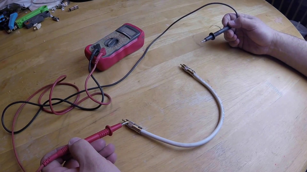
When a cable starts crackling or drops a channel, the place to begin is with a clear diagnosis rather than a hot soldering iron. To check audio cable with multimeter, set your digital meter to continuity or resistance mode and probe the plug contacts against the far-end connections while the cable is completely disconnected from any powered equipment. Often the fault is not a broken wire but a cold or detached solder joint right at the termination, which a simple beep test will reveal in seconds.
If the cable passes continuity but still sounds dull or noisy, you can measure audio cable capacitance by consulting the manufacturer's datasheet for the expected picofarad-per-foot rating and comparing it against your reading. Excessive loading between conductors can roll off high frequencies and is a common sign of moisture damage or a crushed dielectric.
For headphone cables specifically, you can know what audio cable a headphone uses by counting the metal segments on the plug. Three sections indicate a standard TRS connection, while four sections mean you are dealing with a TRRS headset wired to either the CTIA or OMTP standard. You can map this out by testing continuity between each segment and the driver or microphone capsule.
Fixing noise and loose connections
Most crackling, static, and dropouts are not a broken wire deep inside the cable but a poor contact right at the plug. Before you reach for cutters, push the plug firmly into the jack and wiggle it gently while audio plays to see if the noise changes. If a channel cuts in and out only when you flex the plug body, the connector may have an internal fault and the cable may need to be replaced. If you want to fix broken audio cable rather than replace it, knowing how to test and resolder the internal connection can save a perfectly good cable from the bin.
When the problem is persistent background hum or buzz rather than an intermittent crackle, a step to reduce noise from audio cable is to confirm that the shield is actually continuous from plug to plug with your multimeter. A lifted shield braid at the strain relief turns the whole cable into an antenna. In a studio or stage setup, knowing where to use shielded audio cable makes an immediate difference.
If you need to fix staticy audio cable on an iPhone during calls, Apple provides a setting at Settings > Accessibility > Audio/Visual > Phone Noise Cancellation, which is on by default on iPhone 12 and earlier and can be toggled off if it introduces an unwanted processing artifact. Swap in a known-good cable and test with different devices to isolate whether the fault is the cable, the port, or the source device itself. Whether you need to fix broken audio cable on a stage snake or a pair of headphones, the same diagnostic steps apply before you commit to a repair.
Cutting, stripping, and splicing
Before you cut into any jacket, confirm that the fault is actually in the middle of the run and not a loose plug. A clean multimeter check at the terminals will save you from unnecessary surgery. When you do need to strip audio cable, the trick is scoring the outer insulation lightly with a sharp blade and bending the jacket until it snaps, which keeps the braided shield underneath intact instead of nicking the strands. Once the inner conductors are exposed, a gentle twist keeps the fine copper from fraying and sets you up for a solid mechanical joint.
To splice an audio cable for a permanent repair, stagger your cuts so the two solder joints do not sit directly beside each other, and slide a piece of adhesive-lined heat shrink over each connection to prevent shorts. A reliable splice also depends on clean tinning and a steady hand during soldering. If you need to extend audio cable across a room, match the conductor count and shield type exactly, because swapping balanced twisted-pair for a coaxial unbalanced cable mid-run will introduce hum that no plug can fix. Always add a generous service loop at the junction so strain never reaches the splice point.
In a studio or stage setup, you can split audio cable with a simple parallel Y-adapter only for line-level signals. Splitting a single microphone output to feed two preamps without an isolated splitter box will load the capsule incorrectly and degrade the signal, so a transformer-isolated splitter preserves impedance and blocks phantom power conflicts. The iPhone's USB-C connector can be used to play audio through built-in speakers, Bluetooth devices, AirPlay, or supported USB-C audio accessories, so any adapter used in a split or extension must be a powered, compliant device if you are routing from a phone. Passive analog splitters will not work in this digital chain.
Regardless of the modification, always test continuity from tip and sleeve end-to-end before plugging into any powered equipment. A quick resistance check across the shield and inner conductor also catches cold joints and stray wire whiskers, so label your new cable run immediately with length and type so it does not become a mystery line in a crowded patch bay.
Soldering and terminating
When you are ready to attach the connector, the process of how to solder audio cable joints properly starts with trimming all the inner conductors to the same length and stripping back just enough insulation to expose clean copper. Before applying any heat, slip a piece of heat shrink tubing over the raw cable jacket, and consulting a guide on heat shrink sizing for audio cables ensures you match the diameter to your specific plug’s cable entry for strain relief. Lock the hardware in a vise or lay it on a heat-resistant surface so it cannot roll away. Heat the terminal pin and feed the solder directly into the hot metal rather than onto the iron tip. The goal is a shiny, concave fillet that flows into the strands. Once the joint cools, slide the heat shrink into position and shrink it down to insulate the termination and prevent the fine copper from flexing at a single stress point. The same technique applies whether you are terminating audio cables with an XLR, TRS, or RCA plug, and your essential tools do not change: a temperature-controlled iron, the right solder, and a sharp pair of wire strippers. If you need to connect monster audio cable for a digital signal, insert one RCA plug into the source device’s S/PDIF coaxial output and the other into the receiving device’s S/PDIF coaxial input, making sure the plugs seat fully against the jacks.
- heat shrink sizing for audio cables — What Size Heat Shrink For Audio Cable
- connect monster audio cable — How To Connect Monster Audio Cable
- terminating audio cables — What Tool Do You Use To Terminate Audio Cable
- solder audio cable — How To Solder Audio Cable
Building your own cables
Building your own cables opens up projects that go far beyond a simple patch lead, and the same core habits apply whether the job is modest or ambitious. Before cutting any bulk wire, always verify continuity through the plug with a multimeter, because many faults that sound like a dead channel are just one loose solder joint at the termination. For a straightforward speaker run, strip about 3/8 inch of insulation from each lead, twist the bare strands tightly so no whiskers escape, and then connect the positive wire end to the positive terminal on the speaker and amplifier or receiver.
When you move into a DIY audio cable that carries line-level signal, the discipline of testing tip, ring, and sleeve end-to-end before plugging into powered equipment becomes even more critical, since a momentary short can damage sensitive outputs. Always confirm the wiring with your meter first, a habit that saves both time and hardware. If you decide to make an audiophile speaker cable, matching red to red and black to black is the baseline, and terminating with banana plugs, spade lugs, or locking pins gives you a solid, repeatable contact that bare wire cannot match over time. The connection stays gas-tight and resists corrosion, while strain relief at the back of the plug prevents metal fatigue, so a clean mechanical bond matters as much as the solder joint itself.
A related upgrade is to make an audiophile strip electrical outlet box, where the same obsession with clean metal-to-metal contact and secure strain relief determines whether the AC delivery stays quiet under load, so tighten every screw to the manufacturer’s torque specification. In a different corner of the workbench, you might convert a USB data cable to an analog audio cable by harvesting the internal conductors.
Connecting gear correctly
Before you reach for the soldering iron, trace the signal path from its source. When you need to put audio cable in computer, locate the 3.5 mm jacks on the back or front panel, where one is typically the stereo line-out or headphone socket and another marks the microphone input. From there, you typically connect audio cable to speaker by running a shielded lead from that output straight into the RCA or 3.5 mm input on powered speakers, making sure the plug seats all the way home.
If your setup includes a separate audio interface, the routing changes. You will find an input to plug in microphone and audio cable in, and the interface then feeds your computer over USB. For monitoring, the necessary cables for studio monitors are balanced leads running from the interface’s main outputs to each speaker’s input. In a hi-fi chain, deciding which side to preamp connect audiophile cables to comes down to following the signal from a turntable’s output into the phono input, then from the preamp’s line-out to a line-level input on the amplifier. On older machines, you might still need to install a cd rom drive on PC audio cable by connecting an internal analog lead from the drive to the motherboard, though modern systems pass digital audio straight over the SATA bus.
Handling and installing cables
Caring for your cables is just as important as soldering them correctly. Take a moment to properly coil audio cable using the over-under method, which alternates the direction of each loop to avoid twisting the internal conductors. Once the coil lies flat in your hand without springing apart, secure it with a Velcro tie or elastic band, and never knot the cable itself, which can pinch the jacket and break the shield.
If you need to run audio cable on wall surfaces, keep the line low-voltage and physically separated from AC power lines to stop electromagnetic fields from bleeding hum into your signal. Even a neatly coiled spare can turn into a noise antenna if you drop it directly on top of a power amplifier, a transformer, or an outlet strip, so place excess loops off to the side where they will not pick up induced interference. Whether you are tidying a studio patch bay or hiding a home theater feed, these habits preserve the shield integrity that your earlier continuity tests confirmed.